
2 11 月, 2026 • 4 min read
How to Set a CNC Press Brake Backgauge for Complex Bending Sequences
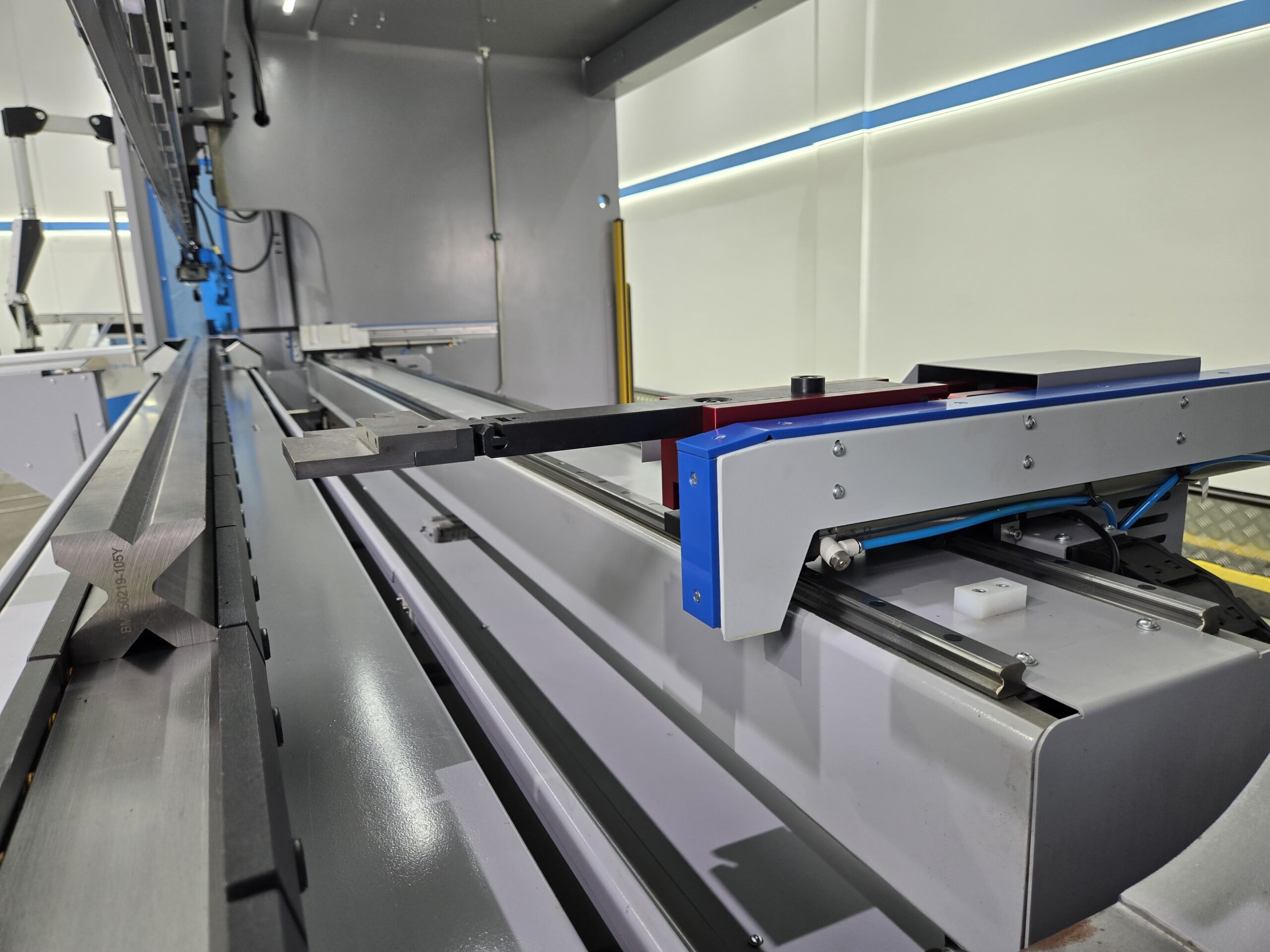
CNC Press Brake Backgauge Setup for Complex Bending
A CNC press brake backgauge is essential for controlling bend positions and achieving consistent flange dimensions. However, when manufacturing complex sheet metal components with multiple bends, setting the backgauge involves much more than entering a single dimension.
For electrical cabinets, industrial enclosures, brackets, and precision sheet metal assemblies, incorrect backgauge settings can lead to dimensional errors, positioning difficulties, or interference between previously formed flanges and the machine.
Understanding backgauge functions and bending sequence planning helps manufacturers improve accuracy and reduce setup time.
What Does a Press Brake Backgauge Do?
A backgauge provides a positioning reference for the sheet metal workpiece before bending.
The operator or automated system positions the material against the backgauge fingers, allowing the press brake to form the bend at the programmed location.
The backgauge primarily controls bend-line positioning and flange dimensions, while the ram position, tooling, and material behavior determine the bending angle.
Modern CNC press brakes may use multiple controlled backgauge axes.
Common axes include:
- X-axis: Front-to-back positioning
- R-axis: Vertical finger positioning
- Z1/Z2 axes: Independent lateral finger positioning
- X1/X2 axes: Independent front-to-back positioning where supported
The actual axis configuration varies by machine model.
Why Complex Bending Requires Careful Planning
A simple bracket with one bend may require only one backgauge position.
A cabinet component with several flanges requires a coordinated sequence of positioning operations.
After the first bend, the workpiece is no longer flat. Previously formed flanges can interfere with the backgauge fingers, tooling, machine frame, or operator handling space.
For this reason, complex bending programs should consider the geometry of the workpiece at every stage.
A theoretically correct bend position may be impossible to achieve if the previous bend blocks access to the required reference surface.
Step 1: Review the Finished Part Drawing
Begin with the complete part drawing rather than individual flange dimensions.
Identify:
- Material thickness
- Bend angles
- Inside bend radii
- Flange lengths
- Overall dimensions
- Hole locations
- Required tolerances
- Potential interference areas
The flat pattern must account for the selected material, tooling, and bend allowance.
Incorrect flat-pattern dimensions cannot be corrected simply by adjusting the backgauge.
Step 2: Determine the Bending Sequence
Bending sequence planning is critical for complex components.
The sequence should allow the workpiece to be positioned safely while avoiding collisions with the punch, die, backgauge, and machine structure.
For many enclosure-type components, shorter internal flanges may need to be formed before larger external flanges.
However, there is no universal bending order.
The correct sequence depends on the part geometry and available tooling.
CNC bending simulation can help identify potential interference before production begins.
Step 3: Select Suitable Backgauge Reference Surfaces
The workpiece must contact the backgauge at a stable and repeatable reference point.
A long straight edge generally provides a more reliable reference than a small tab or irregular contour.
For components containing cutouts, slots, or uneven edges, the backgauge fingers may need to be repositioned.
Independent Z-axis movement can help align the fingers with suitable reference locations.
Where supported, independently controlled X-axis fingers can accommodate certain angled or nonparallel references.
The selected contact points must not cause the sheet to rotate or become unstable.
Step 4: Set the Correct Finger Height
The R-axis controls the vertical position of the backgauge fingers on compatible machines.
Finger height becomes important when positioning workpieces with previously formed flanges.
If the fingers are too low, they may contact an unsuitable surface or fail to provide a stable reference.
If positioned incorrectly, they may interfere with the formed component.
The correct height should be verified using the actual workpiece geometry and tooling setup.
Step 5: Verify the Programmed Dimensions
Before starting production, confirm that the CNC program matches the intended flange dimensions.
Check whether the programmed values refer to:
- Flat-pattern dimensions
- Bend-line positions
- Backgauge contact positions
- Finished flange dimensions
These values are related but are not necessarily identical.
Tooling geometry, material thickness, bend allowance, and springback influence the final result.
A first-piece inspection should confirm the actual dimensions before repetitive production begins.
Step 6: Check Collision Risks
Complex bending introduces several potential collision points.
Previously bent flanges may interfere with the backgauge or machine structure.
Long workpieces may require additional support.
Deep boxes may require special punches or alternative bending sequences.
Before production, verify the bending program using the machine's simulation functions where available, followed by a controlled first-piece setup under the manufacturer's safety procedures.
Never bypass safety systems to accommodate an unsuitable bending sequence.
Step 7: Reduce Setup Time for Small Batches
For job shops processing many different components, setup efficiency can be as important as bending speed.
Useful practices include:
- Standardizing frequently used tooling
- Maintaining accurate tooling libraries
- Saving verified bending programs
- Recording material compensation values
- Using CNC simulation
- Organizing programs by part number
- Maintaining backgauge calibration
These measures can reduce repeated manual adjustments when previously manufactured parts return to production.
What Should Buyers Consider?
When selecting a CNC press brake, evaluate backgauge configuration according to the actual product portfolio.
A basic X/R system may be sufficient for relatively simple components.
Complex cabinets, asymmetric parts, and high-mix production may benefit from additional controlled axes.
However, more axes do not automatically guarantee better accuracy. Machine calibration, software capability, tooling, and operator training remain important.
KLD Machinery offers CNC press brake configurations for different bending requirements, with backgauge and controller options selected according to workpiece complexity and production needs.
Frequently Asked Questions
What is the difference between X-axis and R-axis backgauge movement?
The X-axis controls front-to-back positioning, while the R-axis adjusts finger height on compatible machines.
Do complex bending parts require a 6-axis backgauge?
Not always. The necessary configuration depends on part geometry, reference surfaces, and production requirements.
Why are finished flange dimensions different from programmed dimensions?
Possible causes include incorrect flat patterns, tooling data, material variation, backgauge calibration, or bend allowance.
Can CNC simulation eliminate bending collisions?
Simulation can identify many potential problems, but physical setup verification and safe operating procedures remain necessary.
Conclusion
Accurate backgauge setup requires coordinated planning of the workpiece geometry, bending sequence, tooling, and positioning references.
For complex sheet metal components, a correctly configured CNC backgauge can improve repeatability, reduce setup adjustments, and support more efficient production.
For More Details, Consult Your KLD Sheet Metal Solution Experts
We help you deliver the quality and value required for sheet metal processing equipment.
Consult Our Experts →