10 9 月, 2026 • 4 min read
How 3D Vision Enables Flexible Robotic Bending
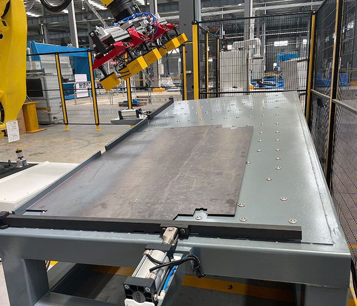
3D vision robotic bending combines industrial vision technology, robotic handling, and CNC press brake automation to support flexible sheet metal production.
Traditional robotic bending systems often rely on workpieces arriving at predefined positions and orientations. When part dimensions, placement, or product types vary, fixed-position automation may require additional mechanical adjustments or programming.
A 3D vision system can help identify workpiece location and orientation, allowing the robot to adjust its handling movements based on detected information.
For manufacturers processing different types of sheet metal components, this capability can improve production flexibility and reduce dependence on precisely positioned incoming materials.
However, successful vision-guided bending requires more than installing a camera.
The vision system must work together with robot programming, gripper design, positioning mechanisms, and the CNC press brake control system.
This KLD application demonstrates how 3D vision technology can be incorporated into a robotic bending cell to support the handling of varied sheet metal workpieces.
The Challenge
The customer was producing large and thick sheet metal components with different dimensions and product types.
A fully fixed automation system would require highly consistent workpiece positioning.
However, when product dimensions vary, the automation system needs additional information to determine where and how the workpiece is positioned.
This is where vision technology becomes valuable.
3D Vision in the Bending Cell
The KLD solution integrates a 3D vision system with a robotic bending cell.
The cell combines:
- CNC press brake
- 6-axis industrial robot
- Robot 7th axis
- 3D vision
- Customized gripper
- Automatic positioning system
- Automatic thickness detection
- Safety guarding
The vision system provides additional information about the workpiece before or during the automated process.
This allows the automation system to work with greater flexibility than a purely fixed-position setup.
How 3D Vision Robotic Bending Works
In a vision-guided robotic bending cell, a 3D vision system captures spatial information about the workpiece before the robot begins its handling sequence.
Depending on the camera technology and software configuration, the system may estimate workpiece position, orientation, and selected geometric features.
The detected information is then processed and transformed into coordinates that the robot can use for positioning and handling.
A typical workflow includes:
- Workpiece detection: The vision system identifies the location and orientation of the incoming sheet metal component.
- Coordinate calculation: Vision software converts the detected position into a reference coordinate system.
- Robot positioning: The robot adjusts its movement to approach the workpiece.
- Workpiece gripping: A suitable gripper secures the component for handling.
- Bending preparation: The robot transfers the workpiece to the required positioning or bending station.
- Bending execution: The press brake performs the programmed bending operation.
- Finished-part handling: The robot transfers the processed component to the designated unloading area.
The actual sequence depends on the equipment configuration, workpiece geometry, and level of automation.
Why 3D Vision Matters for Flexible Production
One of the main advantages of vision-guided automation is its ability to accommodate certain variations in workpiece placement without requiring every part to arrive in exactly the same position.
This is particularly relevant for manufacturers handling multiple component sizes, small production batches, or changing product designs.
However, vision technology does not automatically eliminate all setup requirements.
New workpieces may still require validated robot programs, gripping configurations, bending sequences, and collision checks.
Manufacturers should therefore evaluate the entire bending process rather than treating 3D vision as a standalone solution.
Supporting Flexible Production
The goal of vision integration is not simply to make the robot "see."
The larger objective is to reduce the dependence on perfectly standardized positioning.
For manufacturers producing different sheet metal components, this can be an important step toward flexible automation.
Combined with adjustable positioning equipment and a customized gripping system, 3D vision helps create a production cell capable of dealing with greater variation.
Beyond One Product
A major consideration when investing in automation is future production.
A system designed around only one fixed workpiece may have limited value if the manufacturer's product portfolio changes.
A more flexible architecture can potentially support a wider range of parts.
This is particularly relevant for manufacturers producing:
- Large sheet metal structures
- Heavy panels
- Multiple product sizes
- Different component geometries
- Customized industrial products
The Key Takeaway
3D vision should not be viewed as an isolated technology.
Its value comes from how it works together with:
Robot + Gripper + Positioning + Press Brake + Control System
When these technologies are integrated properly, manufacturers can build bending cells that are more adaptable to real-world production conditions.
KLD Machinery integrates 3D vision, robotic handling, automatic positioning, and CNC bending into customized automation solutions for manufacturers with complex or variable sheet metal production requirements.
Frequently Asked Questions
What is 3D vision robotic bending?
3D vision robotic bending uses industrial vision technology to help a robot identify and handle sheet metal workpieces during automated bending operations.
Can 3D vision recognize different sheet metal parts?
Depending on the camera, software, and system configuration, 3D vision can identify certain workpiece features, positions, and orientations. Recognition capability should be verified using representative production parts.
Does 3D vision eliminate manual positioning?
It can reduce dependence on fixed incoming positions, but some applications still require mechanical positioning, reference fixtures, or additional verification before bending.
Is 3D vision suitable for high-mix, low-volume production?
It can be useful for high-mix manufacturing when the system supports efficient program changes and reliable recognition of different workpieces. Overall suitability depends on part complexity, changeover requirements, and production economics.
For More Details, Consult Your KLD Sheet Metal Solution Experts
We help you deliver the quality and value required for sheet metal processing equipment.
Consult Our Experts →